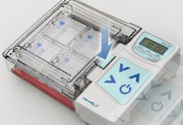
Labnet - Mini Gel II Electrophoresis System
The Mini Gel II electrophoresis system is designed to separate
biological samples such as DNA and proteins. The client wanted to
replace the units they were currently selling, which had been
sourced from another manufacturer, with a new version they could
produce themselves.
To solve this issue, the redesigned unit incorporates a button-
release mechanism that keeps the tank stationary during
separation. The user holds the tank in place, presses the release
button, and slides the power unit away from the tank. By moving
only the power unit instead of pulling on the tank, the design
reduces sudden tank movement and helps prevent solution
splashing.
I began the redesign by focusing on the separation mechanism
between the tank and the power unit. At this stage, the goal was not
to define the final exterior form, but to work through the functional
relationship between the key components.
This allowed me to test different mechanical approaches and
confirm that the separation method could be integrated with the
rest of the system. By resolving the mechanism first, I avoided
designing the product’s exterior too early and then being forced to
fit the functional components into a limited form.
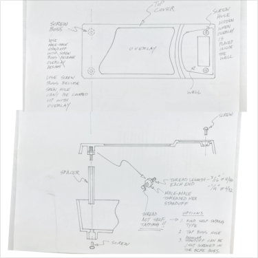
This concept was one of four mechanism directions explored during
the early development phase.
They also wanted to use this redesign as an opportunity to address
one of their customers’ major complaints. On the existing unit,
separating the tank from the power unit required significant force. In
some cases, users could pull too hard, causing the tank to move
suddenly and splash the solution inside.
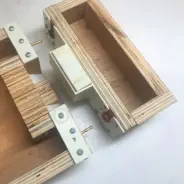
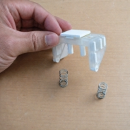
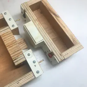
This early mechanism
prototype explored the push-
button release approach that
would become the basis for
the final design.
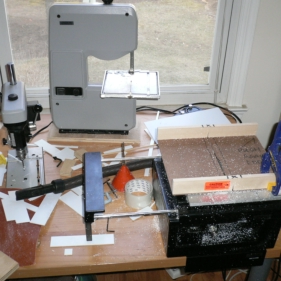
This view shows the model
shop setup used to build the
rough functional prototypes
during the early mechanism
development phase.
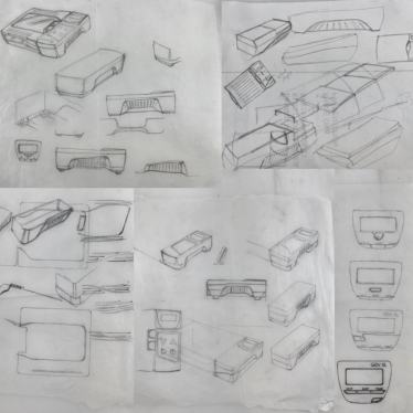
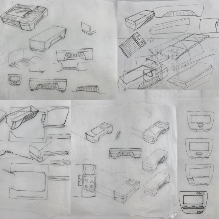
Early sketches exploring the overall form, proportions, and component
relationship between the various parts.
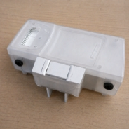
SLS rapid prototype used to evaluate the final form, fit, and
separation mechanism.
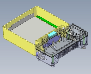
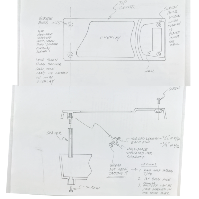
This CAD view shows a later refinement of the release mechanism.
The ejector, shown in purple, pushes against the angled ribs on the
tank. It was widened to spread the applied force more evenly. The
button and ejector were also separated into two parts, allowing the
button press to transfer force more effectively through the ejector.
This wider contact area provided greater mechanical advantage,
making it easier to separate the power unit from the tank in a
controlled way.
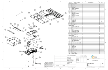
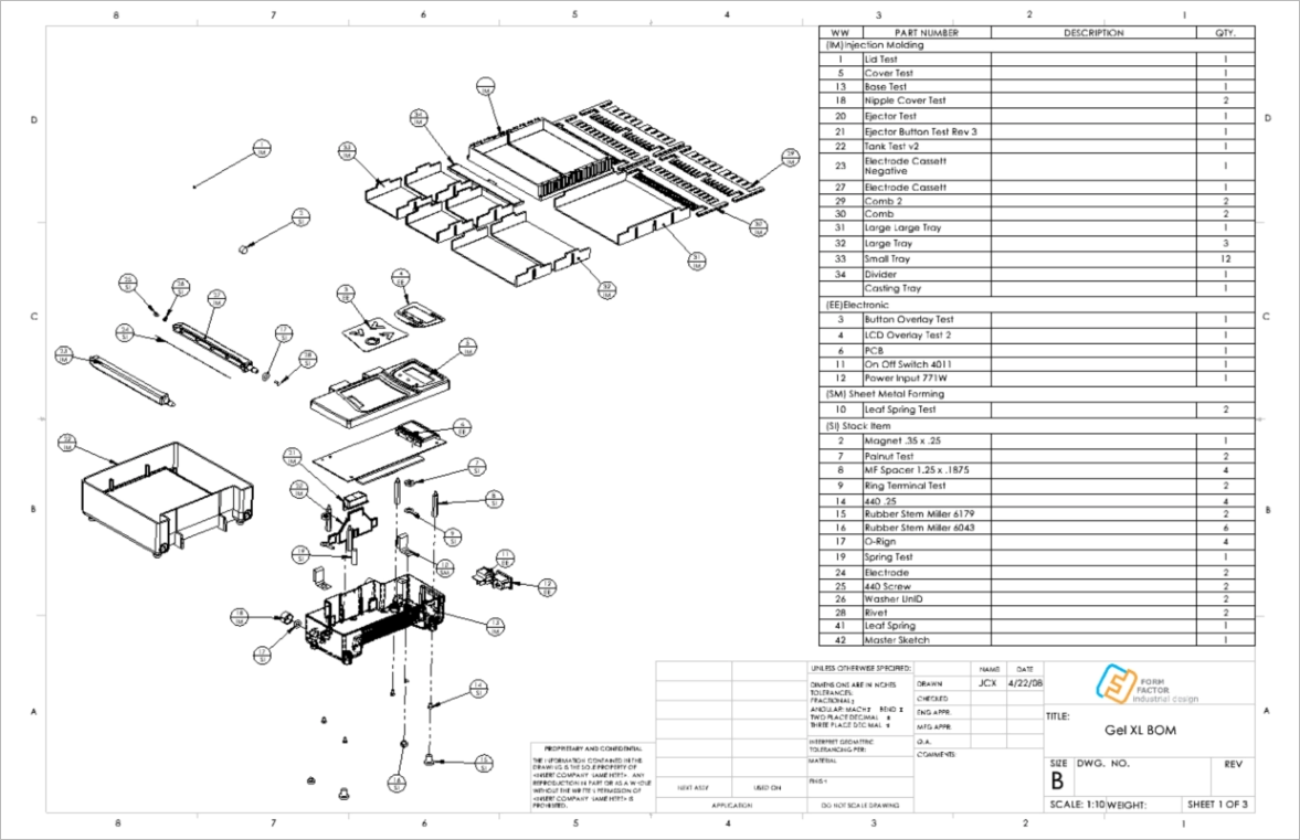
Final engineered CAD model, with all plastic components fully developed
and ready for tooling and injection molding.
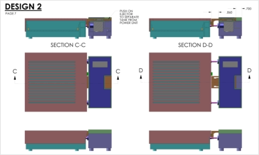
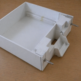
This concept explored a latch-based separation mechanism in which
a downward pivoting latch pushes the power unit away from the
stationary tank.


The Mini Gel II electrophoresis system is designed
to separate biological samples such as DNA and
proteins. The client wanted to replace the units
they were currently selling, which had been
sourced from another manufacturer, with a new
version they were produce themselves. They also
wanted to use this redesign as an opportunity to
address one of their customers’ major
complaints. On the existing unit, separating the
tank from the power unit required significant
force. In some cases, users could pull too hard,
causing the tank to move suddenly and splash
the solution inside.
Labnet - Mini Gel II Electrophoresis System
I began the redesign by focusing on the
separation mechanism between the tank and the
power unit. At this stage, the goal was not to
define the final exterior form, but to work through
the functional relationship between the key
components.
This allowed me to test different mechanical
approaches and confirm that the separation
method could be integrated with the rest of the
system. By resolving the mechanism first, I
avoided designing the product’s exterior too early
and then being forced to fit the functional
components into a limited form.
This view shows the
model shop setup used
to build the rough
functional prototypes
during the early
mechanism
development phase.
Early sketches exploring the overall form,
proportions, and component relationship between
the various parts.
SLS rapid prototype used to evaluate the final
form, fit, and separation mechanism.
This CAD view shows a later refinement of the
release mechanism. The ejector, shown in purple,
pushes against the angled ribs on the tank. It was
widened to spread the applied force more evenly.
The button and ejector were also separated into
two parts, allowing the button press to transfer
force more effectively through the ejector. This
wider contact area provided greater mechanical
advantage, making it easier to separate the power
unit from the tank in a controlled way.
Final engineered CAD model, with all plastic
components fully developed and ready for tooling
and injection molding.
This concept explored a latch-based separation
mechanism in which a downward pivoting latch
pushes the power unit away from the stationary
tank.
To solve this issue, the redesigned unit
incorporates a button-release mechanism that
keeps the tank stationary during separation.
The user holds the tank in place, presses the
release button, and slides the power unit away
from the tank. By moving only the power unit
instead of pulling on the tank, the design reduces
sudden tank movement and helps prevent
solution splashing.
This concept was one of four mechanism
directions explored during the early development
phase.
This early mechanism
prototype explored the
push-button release
approach that would
become the basis for
the final design.